6.6 Interference and Diffraction
10 min read•january 1, 2023
Daniella Garcia-Loos
Saarah Hasan
Daniella Garcia-Loos
Saarah Hasan
Light Waves
Light’s ability to diffract and display interference is clear evidence of its wavelike nature. When waves meet in phase (crest meets crest), they display constructive interference; if they meet out of phase (crest meets trough), they display destructive interference. These interference patterns can be observed in light by using two or more narrow slits (we’ll get into this more in a bit).
When waves that have the same wavelength interfere with each other, the difference in the distances they’ve traveled determine whether they’re in phase or out of phase. If the difference of their path lengths, ΔlΔl, is a whole number of wavelengths, then the waves will meet in phase. If the difference is a whole number plus ½ of a wavelength, then the waves will meet out of phase.
Constructive Interference: Δl=mλ
Where m = 0,1,2…m=0,1,2…
Destructive Interference:Δl=(m+½)λ
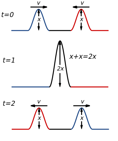
Constructive Interference Taken from Wikipedia
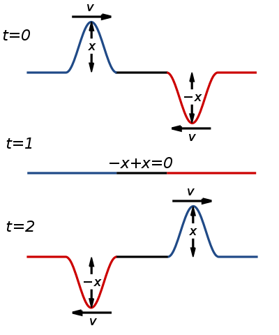
Destructive Interference Taken from Wikimedia Commons
Here are some key points about constructive and destructive interference:
Interference is the phenomenon that occurs when two or more waves overlap. Interference can either enhance or cancel out the amplitude of the waves, depending on the phase relationship between the waves.
Constructive interference occurs when the amplitudes of two or more waves combine to produce a wave with a greater amplitude. This occurs when the waves are in phase, or when the difference in their phase is an integer multiple of 2π.
Destructive interference occurs when the amplitudes of two or more waves combine to produce a wave with a smaller amplitude. This occurs when the waves are out of phase, or when the difference in their phase is an odd integer multiple of π.
Constructive and destructive interference can be observed in a variety of situations, including sound waves, light waves, and water waves.
The intensity of interference is determined by the relative amplitudes and phases of the interfering waves. The intensity of constructive interference is maximized when the amplitudes of the interfering waves are equal, and the intensity of destructive interference is maximized when the amplitudes of the interfering waves are equal and opposite.
Thomas Young’s Double-Slit Experiment
Let’s expand a bit more on : what is it? You can think of as the spreading of waves when they meet an obstacle/slit. This is easily observable when a wave from a coherent(which means that the phase difference of the wave remains constant) source passes through a slit that’s similar in size to its wavelength.
Taken from Wikimedia Commons
So what was ’s experiment? Young sent light from the left side of a screen towards two small openings. If light was simply a particle, then it would’ve traveled as two narrow strips, directly opposite the slits in the barrier. But that’s not what happened, as you can see above.
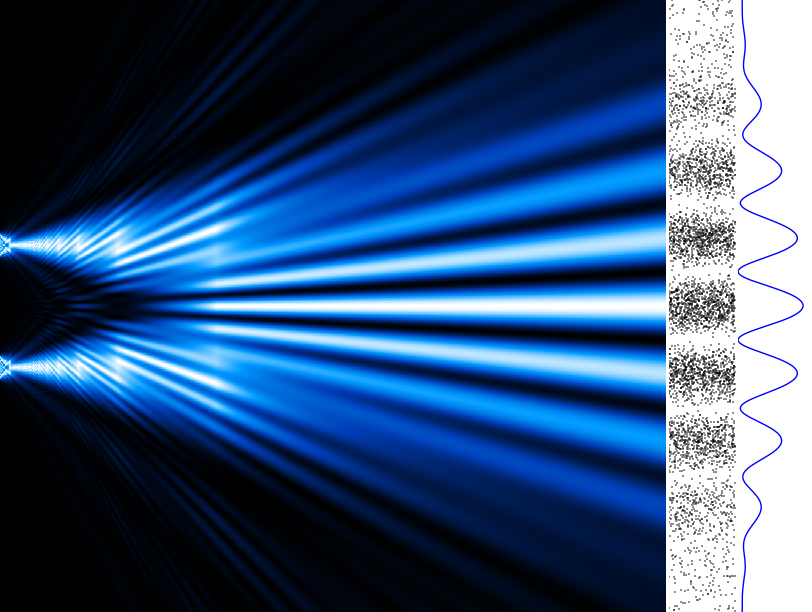
If monochromatic coherent light travels through two close small slits, then it diffracts through them, interfering with itself and creating interference patterns, as shown below. The light continues to exhibit this wave nature as it spreads.
Taken from Wikimedia Commons
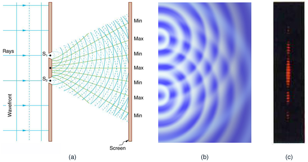
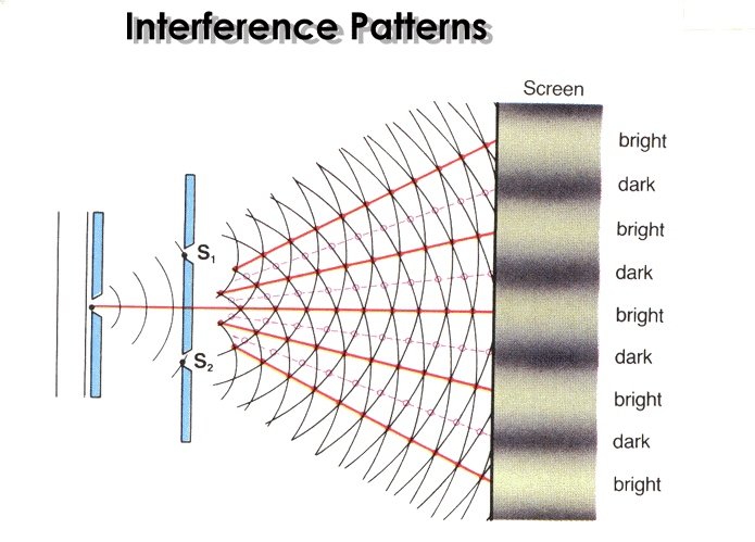
Taken from openstax.org
In the figure above, you can see the points of constructive and destructive interference. The points where the solid lines intersect with the other solid lines are points of constructive interference. The points where the solid lines intersect with the dashed lines are points of destructive interference.
In the figure above, you can see the points of constructive and destructive interference. The points where the solid red lines intersect with the other solid lines are points of constructive interference. The points where the dashed red lines intersect with the solid lines are points of destructive interference.
The screen shows the results of this interference. We get bright bands/spots where the waves interfere constructively; where the waves interfere destructively, we get dark bands/spots. The equations we use to find these fringes are:
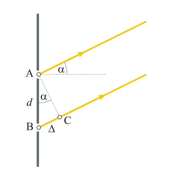
We use different symbols below, so know that we mean α is θ and thatΔ is dsinθ Taken from Wikimedia Commons
Constructive Interference: dsinθ=mλ
(intensity maximum bright fringe on screen)
m=0,1,2,3...
Destructive Interference: dsinθ=(m+½λ)
(intensity minimum dark fringe on screen)
Where
- d=distance between the slits
- θ=angle from the central beam to the next
- λ=wavelength
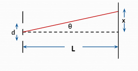
If θ is really small, the hypotenuse is nearly equal to L(small angle approximation).
From that we can turn
dsinθ=mλ into d(x/L)=mλ
We can rearrange this expression to get one that describes the distance between the fringes:
x=mλL/d
Here's an interactive where you can do Young's experiment yourself.
Important ideas to keep in mind:
- Light diffracts through an opening if the wavelength is on the right side
- Wavelength, slit spacing, and distance affect
- When waves pass by an edge, they can diffract into the “shadow region” behind the edge. To sort of visualize this, think about how you can hear around corners without seeing around them and how water waves bend around obstacles.
Thin Film Interference
When light travels across mediums, some of it reflects and some crosses the boundary. The light that gets reflected may undergo a -the wave will flip. If n_2 is greater than n_1n, there will be 180 degrees.
Taken from Wikimedia Commons
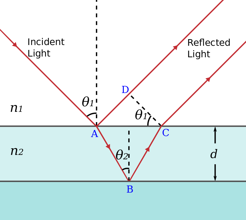
When light passes through a very thin material (such as a soap bubble or a piece of glass) some of it refracts, some of it reflects off the top and undergoes a , some of the light reflects off of the back of the film and then refracts out the other side. This will all probably sound really confusing, so let’s take a look at a picture to simplify.
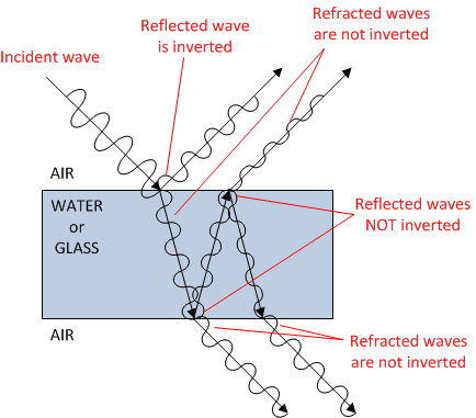
Taken from physics.stackexchange.com
In the figure above, when light hits the thin material, some of it is reflected from the first surface (front) and some from the secondary surface (back). Some of the reflected waves interfere constructively, making those wavelengths more intense. Some interfere destructively; their wavelengths are absent from the reflection.
Keep in mind that the wave that’s reflected from the front undergoes a 180^o 180o, but the wave reflected from the back doesn’t. The total distance that the wave travels is twice the thickness of the material.
For destructive interference- the total distance traveled must be a multiple of a whole wavelength.
For constructive interference- the total distance traveled must be an odd multiple of half a wavelength.
Now, how do we calculate the wavelength inside the material? We start off with this equation, which hopefully looks familiar:
n_1λ_1=n_2λ_2
The of the first substance * the wavelength of light through that first substance = The of the second substance * the wavelength of light through the second substance.
The λ in the material, however, is different from λ in the air
λ_n=λ/n
where
λ_n= wavelength in the material
λ= wavelength in air
n= of the material
The thickness of the material:
Destructive: t(min)=½ λ_n
Also occurs if the thickness is λ, 1.5λ, 2λ, 2.5λ…
Constructive: t(min)=¼ λ_n
Also occurs if the thickness is 0.75λ, 1.25λ, 1,75λ, 2.25λ…
Here are some key points to remember about :
is the phenomenon that occurs when light reflects off the top and bottom surfaces of a thin film of material, such as a layer of oil on water.
The thickness of the film and the refractive indices of the film and the surrounding medium determine the phase difference between the light waves reflected from the top and bottom surfaces of the film.
When the thickness of the film is an integer multiple of the wavelength of the light, constructive interference occurs, resulting in a bright fringe. When the thickness of the film is an odd integer multiple of half the wavelength of the light, destructive interference occurs, resulting in a dark fringe.
The colors of the fringes depend on the thickness of the film and the refractive indices of the film and the surrounding medium.
can be observed using a variety of techniques, including a , a , and a reflection interference microscope.
Practice Problems:
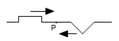
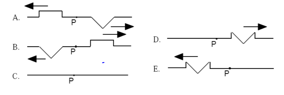
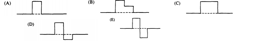
1. Two waves pulses approach each other as seen in the figure. The wave pulses overlap at point P. Which diagram best represents the appearance of the wave pulses as they leave point P?
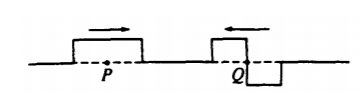
2. The figure above shows two wave pulses that are approaching each other. Which of the following best shows the shape of the resultant pulse when the centers of the pulses, points P and Q coincide?
3. A student performs an experiment similar to Young’s Double Slit Experiment. Coherent light passes through two narrow slits and produces a pattern of alternating bright and dark lines on a screen. Which of the following would cause the bright lines on the screen to be further apart? I. Increasing the distance between the slits II. Decreasing the distance between the slits III. Decreasing the wavelength of the light
A) I only
B) II only
C) III only
D) I & III only
E) II & III only
4. In a Young's , the slit separation is doubled. To maintain the same fringe spacing on the screen, the screen-to-slit distance D must be changed to
A) D/2
B)2/√D
C) D√2
D) 2D
E) 4D
5. In an experiment to measure the wavelength of light using a double slit apparatus, it is found that the bright fringes are too close together to easily count them. To increase only the spacing between the bright fringes, one could
A) increase the slit width
B) decrease the slit width
C) increase the slit separation
D) decrease the slit separation
6.
Answers:
B: After waves interfere they move along as if they never met
A: Use superposition and overlap the waves to see the resultant
A: The given diagram is the 3rd harmonic at 60 Hz. That means the fundamental is 20Hz. The other possible standing waves should be multiples of 20
D: To use v = f λ, you also need the λ
B: Using f_n=nv/2L with n = 1, solve for L
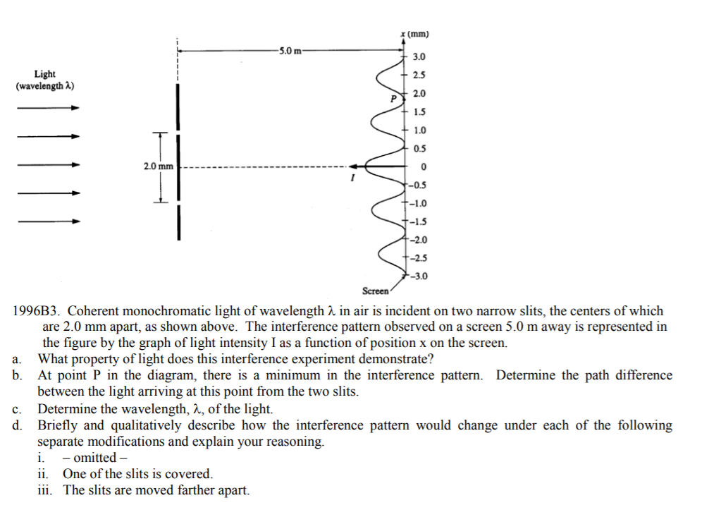
a. The fact that light interferes means it’s a wave (this will be discussed more in the modern physics topic)
b. Looking at the intensity pattern, P is the second point of zero intensity which means it’s the 2nd dark spot (m=1.5). Using Path Diff = mλ … m λ = d x / L … path diff = (2x10^–^3) (1.8x10^–^3) / 5 … path diff = 7.2x10^–^7 m
c. Path Diff = mλ … 7.2x10^–^7 = 1.5 λ … λ = 4.8x10^–^7 m
d.
i. Based on n_1 λ_1 = n_2 λ_2 …n_airλ_air= n_water λ_water. The λ_water is less in comparison to the air. So the λ has been decreased. In the equation m λ = d x / L, for decreased λ there will be decreased x, which means the location of spots is smaller, compressing the pattern.
ii. Covering a slit makes this a single slit pattern. In the single slit, m=1 becomes the first dark region (the end of the central bright spot) instead of m=0.5 being the end of the central bright spot. All of the other integer m’s also become dark spot locations. The effect of this is to make the central max wider and widen the pattern. Additionally, in single slit , the intensities generally lose intensity more rapidly when moving away from the center
iii. Increasing d. Based on mλ = d x / L, this would make x less so would compress the pattern.
Key Terms to Review (10)
Coherent Source
: A coherent source refers to a source that emits waves with a constant phase relationship. In other words, the crests and troughs of the waves are aligned and maintain their positions over time.Diffraction
: Diffraction is the bending or spreading of waves around obstacles or through narrow openings.Double-slit experiment
: The double-slit experiment is a classic physics experiment that demonstrates the wave-particle duality of light and matter. It involves shining a beam of particles or waves through two closely spaced slits, resulting in an interference pattern on a screen behind them.Fabry-Pérot Interferometer
: A Fabry-Pérot Interferometer is an optical device that uses interference to measure the wavelength of light or the thickness of transparent materials. It consists of two parallel mirrors with a small gap in between, allowing light to enter and reflect multiple times.Index of Refraction
: The index of refraction is a measure of how much light slows down when it passes through a medium. It quantifies the bending or change in direction that occurs as light travels from one medium to another.Michelson Interferometer
: A Michelson interferometer is an instrument that uses the principle of interference to measure small displacements, wavelengths, or refractive indices. It splits a beam of light into two paths, recombines them, and produces an interference pattern that can be analyzed.Monochromatic Light
: Monochromatic light refers to light that consists of a single wavelength or color. It is composed of photons with the same frequency.Phase Change
: Phase change refers to the transition between different states (phases) of matter, such as solid, liquid, gas, or plasma. During phase changes, energy is either absorbed or released while temperature remains constant.Thin Film Interference
: Thin film interference occurs when light waves reflecting off both surfaces of a thin film interfere with each other constructively or destructively. This interference creates colorful patterns or changes in brightness.Thomas Young
: Thomas Young was a British scientist who made significant contributions to the understanding of light and wave behavior. He is best known for his double-slit experiment, which demonstrated the wave nature of light.6.6 Interference and Diffraction
10 min read•january 1, 2023
Daniella Garcia-Loos
Saarah Hasan
Daniella Garcia-Loos
Saarah Hasan
Light Waves
Light’s ability to diffract and display interference is clear evidence of its wavelike nature. When waves meet in phase (crest meets crest), they display constructive interference; if they meet out of phase (crest meets trough), they display destructive interference. These interference patterns can be observed in light by using two or more narrow slits (we’ll get into this more in a bit).
When waves that have the same wavelength interfere with each other, the difference in the distances they’ve traveled determine whether they’re in phase or out of phase. If the difference of their path lengths, ΔlΔl, is a whole number of wavelengths, then the waves will meet in phase. If the difference is a whole number plus ½ of a wavelength, then the waves will meet out of phase.
Constructive Interference: Δl=mλ
Where m = 0,1,2…m=0,1,2…
Destructive Interference:Δl=(m+½)λ
Constructive Interference Taken from Wikipedia
Destructive Interference Taken from Wikimedia Commons
Here are some key points about constructive and destructive interference:
Interference is the phenomenon that occurs when two or more waves overlap. Interference can either enhance or cancel out the amplitude of the waves, depending on the phase relationship between the waves.
Constructive interference occurs when the amplitudes of two or more waves combine to produce a wave with a greater amplitude. This occurs when the waves are in phase, or when the difference in their phase is an integer multiple of 2π.
Destructive interference occurs when the amplitudes of two or more waves combine to produce a wave with a smaller amplitude. This occurs when the waves are out of phase, or when the difference in their phase is an odd integer multiple of π.
Constructive and destructive interference can be observed in a variety of situations, including sound waves, light waves, and water waves.
The intensity of interference is determined by the relative amplitudes and phases of the interfering waves. The intensity of constructive interference is maximized when the amplitudes of the interfering waves are equal, and the intensity of destructive interference is maximized when the amplitudes of the interfering waves are equal and opposite.
Thomas Young’s Double-Slit Experiment
Let’s expand a bit more on : what is it? You can think of as the spreading of waves when they meet an obstacle/slit. This is easily observable when a wave from a coherent(which means that the phase difference of the wave remains constant) source passes through a slit that’s similar in size to its wavelength.
Taken from Wikimedia Commons
So what was ’s experiment? Young sent light from the left side of a screen towards two small openings. If light was simply a particle, then it would’ve traveled as two narrow strips, directly opposite the slits in the barrier. But that’s not what happened, as you can see above.
If monochromatic coherent light travels through two close small slits, then it diffracts through them, interfering with itself and creating interference patterns, as shown below. The light continues to exhibit this wave nature as it spreads.
Taken from Wikimedia Commons
Taken from openstax.org
In the figure above, you can see the points of constructive and destructive interference. The points where the solid lines intersect with the other solid lines are points of constructive interference. The points where the solid lines intersect with the dashed lines are points of destructive interference.
In the figure above, you can see the points of constructive and destructive interference. The points where the solid red lines intersect with the other solid lines are points of constructive interference. The points where the dashed red lines intersect with the solid lines are points of destructive interference.
The screen shows the results of this interference. We get bright bands/spots where the waves interfere constructively; where the waves interfere destructively, we get dark bands/spots. The equations we use to find these fringes are:
We use different symbols below, so know that we mean α is θ and thatΔ is dsinθ Taken from Wikimedia Commons
Constructive Interference: dsinθ=mλ
(intensity maximum bright fringe on screen)
m=0,1,2,3...
Destructive Interference: dsinθ=(m+½λ)
(intensity minimum dark fringe on screen)
Where
- d=distance between the slits
- θ=angle from the central beam to the next
- λ=wavelength
If θ is really small, the hypotenuse is nearly equal to L(small angle approximation).
From that we can turn
dsinθ=mλ into d(x/L)=mλ
We can rearrange this expression to get one that describes the distance between the fringes:
x=mλL/d
Here's an interactive where you can do Young's experiment yourself.
Important ideas to keep in mind:
- Light diffracts through an opening if the wavelength is on the right side
- Wavelength, slit spacing, and distance affect
- When waves pass by an edge, they can diffract into the “shadow region” behind the edge. To sort of visualize this, think about how you can hear around corners without seeing around them and how water waves bend around obstacles.
Thin Film Interference
When light travels across mediums, some of it reflects and some crosses the boundary. The light that gets reflected may undergo a -the wave will flip. If n_2 is greater than n_1n, there will be 180 degrees.
Taken from Wikimedia Commons
When light passes through a very thin material (such as a soap bubble or a piece of glass) some of it refracts, some of it reflects off the top and undergoes a , some of the light reflects off of the back of the film and then refracts out the other side. This will all probably sound really confusing, so let’s take a look at a picture to simplify.
Taken from physics.stackexchange.com
In the figure above, when light hits the thin material, some of it is reflected from the first surface (front) and some from the secondary surface (back). Some of the reflected waves interfere constructively, making those wavelengths more intense. Some interfere destructively; their wavelengths are absent from the reflection.
Keep in mind that the wave that’s reflected from the front undergoes a 180^o 180o, but the wave reflected from the back doesn’t. The total distance that the wave travels is twice the thickness of the material.
For destructive interference- the total distance traveled must be a multiple of a whole wavelength.
For constructive interference- the total distance traveled must be an odd multiple of half a wavelength.
Now, how do we calculate the wavelength inside the material? We start off with this equation, which hopefully looks familiar:
n_1λ_1=n_2λ_2
The of the first substance * the wavelength of light through that first substance = The of the second substance * the wavelength of light through the second substance.
The λ in the material, however, is different from λ in the air
λ_n=λ/n
where
λ_n= wavelength in the material
λ= wavelength in air
n= of the material
The thickness of the material:
Destructive: t(min)=½ λ_n
Also occurs if the thickness is λ, 1.5λ, 2λ, 2.5λ…
Constructive: t(min)=¼ λ_n
Also occurs if the thickness is 0.75λ, 1.25λ, 1,75λ, 2.25λ…
Here are some key points to remember about :
is the phenomenon that occurs when light reflects off the top and bottom surfaces of a thin film of material, such as a layer of oil on water.
The thickness of the film and the refractive indices of the film and the surrounding medium determine the phase difference between the light waves reflected from the top and bottom surfaces of the film.
When the thickness of the film is an integer multiple of the wavelength of the light, constructive interference occurs, resulting in a bright fringe. When the thickness of the film is an odd integer multiple of half the wavelength of the light, destructive interference occurs, resulting in a dark fringe.
The colors of the fringes depend on the thickness of the film and the refractive indices of the film and the surrounding medium.
can be observed using a variety of techniques, including a , a , and a reflection interference microscope.
Practice Problems:
1. Two waves pulses approach each other as seen in the figure. The wave pulses overlap at point P. Which diagram best represents the appearance of the wave pulses as they leave point P?
2. The figure above shows two wave pulses that are approaching each other. Which of the following best shows the shape of the resultant pulse when the centers of the pulses, points P and Q coincide?
3. A student performs an experiment similar to Young’s Double Slit Experiment. Coherent light passes through two narrow slits and produces a pattern of alternating bright and dark lines on a screen. Which of the following would cause the bright lines on the screen to be further apart? I. Increasing the distance between the slits II. Decreasing the distance between the slits III. Decreasing the wavelength of the light
A) I only
B) II only
C) III only
D) I & III only
E) II & III only
4. In a Young's , the slit separation is doubled. To maintain the same fringe spacing on the screen, the screen-to-slit distance D must be changed to
A) D/2
B)2/√D
C) D√2
D) 2D
E) 4D
5. In an experiment to measure the wavelength of light using a double slit apparatus, it is found that the bright fringes are too close together to easily count them. To increase only the spacing between the bright fringes, one could
A) increase the slit width
B) decrease the slit width
C) increase the slit separation
D) decrease the slit separation
6.
Answers:
B: After waves interfere they move along as if they never met
A: Use superposition and overlap the waves to see the resultant
A: The given diagram is the 3rd harmonic at 60 Hz. That means the fundamental is 20Hz. The other possible standing waves should be multiples of 20
D: To use v = f λ, you also need the λ
B: Using f_n=nv/2L with n = 1, solve for L
a. The fact that light interferes means it’s a wave (this will be discussed more in the modern physics topic)
b. Looking at the intensity pattern, P is the second point of zero intensity which means it’s the 2nd dark spot (m=1.5). Using Path Diff = mλ … m λ = d x / L … path diff = (2x10^–^3) (1.8x10^–^3) / 5 … path diff = 7.2x10^–^7 m
c. Path Diff = mλ … 7.2x10^–^7 = 1.5 λ … λ = 4.8x10^–^7 m
d.
i. Based on n_1 λ_1 = n_2 λ_2 …n_airλ_air= n_water λ_water. The λ_water is less in comparison to the air. So the λ has been decreased. In the equation m λ = d x / L, for decreased λ there will be decreased x, which means the location of spots is smaller, compressing the pattern.
ii. Covering a slit makes this a single slit pattern. In the single slit, m=1 becomes the first dark region (the end of the central bright spot) instead of m=0.5 being the end of the central bright spot. All of the other integer m’s also become dark spot locations. The effect of this is to make the central max wider and widen the pattern. Additionally, in single slit , the intensities generally lose intensity more rapidly when moving away from the center
iii. Increasing d. Based on mλ = d x / L, this would make x less so would compress the pattern.
Key Terms to Review (10)
Coherent Source
: A coherent source refers to a source that emits waves with a constant phase relationship. In other words, the crests and troughs of the waves are aligned and maintain their positions over time.Diffraction
: Diffraction is the bending or spreading of waves around obstacles or through narrow openings.Double-slit experiment
: The double-slit experiment is a classic physics experiment that demonstrates the wave-particle duality of light and matter. It involves shining a beam of particles or waves through two closely spaced slits, resulting in an interference pattern on a screen behind them.Fabry-Pérot Interferometer
: A Fabry-Pérot Interferometer is an optical device that uses interference to measure the wavelength of light or the thickness of transparent materials. It consists of two parallel mirrors with a small gap in between, allowing light to enter and reflect multiple times.Index of Refraction
: The index of refraction is a measure of how much light slows down when it passes through a medium. It quantifies the bending or change in direction that occurs as light travels from one medium to another.Michelson Interferometer
: A Michelson interferometer is an instrument that uses the principle of interference to measure small displacements, wavelengths, or refractive indices. It splits a beam of light into two paths, recombines them, and produces an interference pattern that can be analyzed.Monochromatic Light
: Monochromatic light refers to light that consists of a single wavelength or color. It is composed of photons with the same frequency.Phase Change
: Phase change refers to the transition between different states (phases) of matter, such as solid, liquid, gas, or plasma. During phase changes, energy is either absorbed or released while temperature remains constant.Thin Film Interference
: Thin film interference occurs when light waves reflecting off both surfaces of a thin film interfere with each other constructively or destructively. This interference creates colorful patterns or changes in brightness.Thomas Young
: Thomas Young was a British scientist who made significant contributions to the understanding of light and wave behavior. He is best known for his double-slit experiment, which demonstrated the wave nature of light.Resources
© 2024 Fiveable Inc. All rights reserved.
AP® and SAT® are trademarks registered by the College Board, which is not affiliated with, and does not endorse this website.